 |
| Door On |
 |
| Doors Off - BEFORE |
 |
| Doors Off - NOW! |

So back to the install... in total, this was a very easy project. The instructions are a really well written and it takes under an hour to complete it. My purpose in replacing my old links was that they were moved from the rear of my JL when I did the lift. They did not fit as they should, were not adjustable, and I honestly did not like they way they looked.

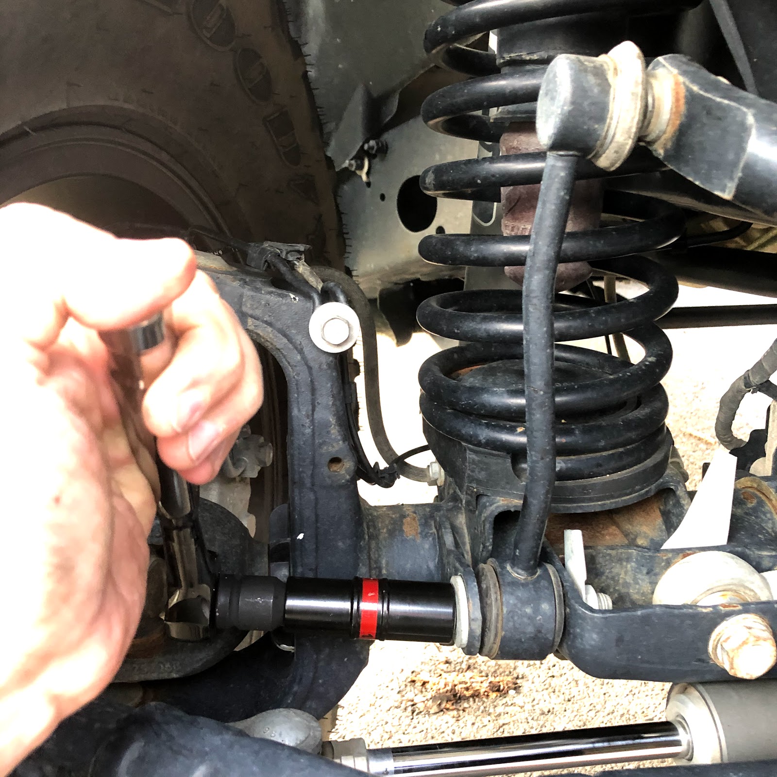
I wanted to upgrade to an adjustable link that was durable and I think I found exactly what I wanted with these Clayton links. The first step is to remove your old links. This is an easy task but I found that if you remove both bottom bolts first, you can push down the sway bar and easily remove both top bolts.
Once these are out, the next step is to align you sway bar about 5 degrees up and I used a carpenters angle finder to accomplish this. It worked really well if you know your vehicle is on level ground.


This is the only part I struggled with a bit so what worked for me was to line up the old link and the new ones next to each other and determine the proper places to make the cuts. My handy Hitachi Grinder with Diablo blade made a nice clean quick cut. From here, it becomes an easy task to assemble the ends and mount the newly fitted links. On the Drivers side, you will be using both ends (top and bottom) with the ends that have the studs on them. On the passenger side, you will use the end with the stud on the top and the non-studded end on the bottom with the two aluminum spacers on each side. Both arms get installed with the studs facing inward and as I said in the beginning, start with both tops and mount them first with the sway bar positioned all the way down so it is east to tighten everything down (torqued to 60 ft-pd). Then raise the sway bar back up and mount the lower stud on the drivers side. I used the OEM provided bolt and nut on the passenger side and everything worked great. The only thing I did not need to do, that was part of the instructions, was to "Drill hole in sway bar to 1/2" diameter". Everything fit well without doing this step.


The Journey is what counts, Adventure Awaits!
No comments:
Post a Comment